# 电缆布线基础知识
电缆是常见的 电磁干扰 (打开新窗口)这可能会导致飞行偏移、"厕所保龄球 "和普遍飞行不良等问题。在无人机中使用适当的电缆可以避免这些问题。
设计无人机布线时应牢记以下基本概念:
- 大功率电缆和信号电缆应尽可能分开。
- 电线长度应为所需的最小长度,以便于处理接线组件。电线张力应足以承受机身可能发生的变形,即使是在迫降时(电线不能首先断裂)。
- 应避免为减少多余长度而将电缆缠绕在一起 - 使用较短的长度!
- 对于数字信号,您可以降低波特率,以减少辐射能量并提高数据传输的稳健性。这意味着在不需要高数据传输速率时,可以使用较长的电缆。
# 信号接线
信号协议具有不同的特性,因此每种情况下使用的电缆所要求的规格也略有不同。
本主题为不同信号协议的布线提供具体指导,以及 颜色编码 由多家不同的无人机硬件供应商使用。
# I2C 电缆
I2C 总线 (打开新窗口) 广泛用于连接传感器。下表列出了几家供应商提供的电缆颜色。
| 信号 | Pixhawk 颜色 | ThunderFly 颜色 | CUAV 颜色(I2C/CAN) |
|---|---|---|---|
| +5V |  红色 红色 | 红色 | 红色 |
| SCL |  黑色 黑色 |  黄色 黄色 |  白色 白色 |
| SDA | 黑色 |  绿色 绿色 | 黄色 |
| 接地 | 黑色 | 黑色 | 黑色 |
Dronecode 标准 (打开新窗口) 假设自动驾驶仪的 SDA 和 SCL 信号上有 1.5k 欧姆的上拉电阻。
# 电缆缠绕
通过适当扭转电缆线,可大大改善 I2C 总线信号串扰和电磁兼容性。 双绞线 (打开新窗口) 这对传感器布线尤为重要。
- 每对 SCL/+5V 和 SDA/GND 每 30 厘米电缆长度 10 圈。
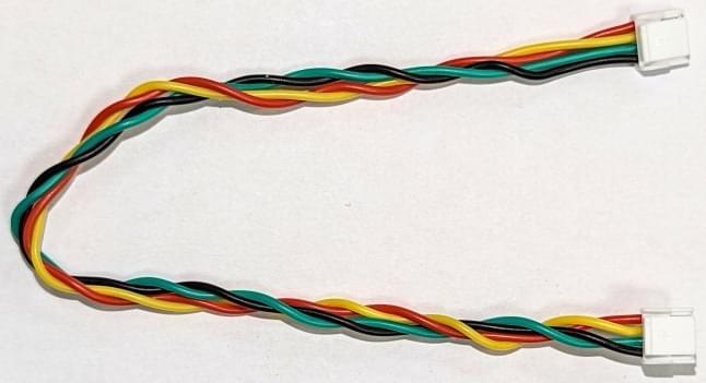
- 每 30 厘米电缆长度,两对电缆共转 4 圈。
使用适当的双绞线时,I²C 总线通常适用于亚米级机身。对于大型飞机,使用 CAN 或其他基于差分信号的接口通常更为可靠。
备注
这种匝数/电缆长度建议已成功用于 I2C 传感器,包括 ThunderFly TFSLOT 空速传感器 和 TFRPM01 转速计数器.
# 上拉电阻
I2C 总线的两端都需要上拉电阻。这既是 信号终止 (打开新窗口) 和总线空闲信号发生器。
有时需要使用示波器进行测量,以检查上拉电阻的正确值。I2C 总线上的信号应具有清晰锐利的矩形边缘和几伏的振幅。如果信号振幅较低,则说明上拉电阻的值过低,应适当降低。如果信号呈圆形,则上拉电阻值过高。
# UAVCAN 电缆
| 信号 | Pixhawk | 雷飞 | 祖巴茨 | CUAV(I2C/CAN) |
|---|---|---|---|---|
| +5V | 红色 | 红色 | 红色 | 红色 |
| CAN_H | 黑色 | 白色 | 白色 | 白色 |
| CAN_L | 黑色 | 黄色 | 黄色 | 黄色 |
| 接地 | 黑色 | 黑色 | 黑色 | 黑色 |
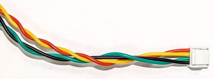
# 电缆缠绕
CAN 电缆也应扭曲,原因与 I2C 电缆完全相同。对于 CAN 电缆,建议的扭绞方式是
每对 GND/+5V 和 CAN_L/CAN_H(每 30 厘米电缆长度)10 圈。
每 30 厘米电缆长度,两对电缆共转 4 圈。
# SPI
SPI (打开新窗口) 是同步串行通信接口,用于连接速度更快的传感器和设备。该协议通常用于连接 光流 传感器或特殊遥测调制解调器。
| 信号 | Pixhawk 颜色 | 雷飞颜色 |
|---|---|---|
| +5V | 红色 | 红色 |
| SCK | 黑色 | 黄色 |
| MISO | 黑色 |  蓝色 蓝色 |
| MOSI | 黑色 | 绿色 |
| CS! | 黑色 | 白色 |
| CS2 | 黑色 | 蓝色 |
| 接地 | 黑色 | 黑色 |
# UART
UART 用于将外围设备连接到自动驾驶仪。默认情况下,UART 不支持联网,因此可直接将两个设备连接在一起。它通常用于连接自动驾驶仪和 无线电调制解调器.
CTS 和 RTS 信号用于指示 TX/RX 引脚上的数据正在传输。这种握手机制提高了数据传输的可靠性。当设备不使用时,CTS 和 RTS 可能保持松动。
连接电缆不交叉。因此,只需用这条直电缆连接自动驾驶仪和外围设备。设备必须通过交换 RX/TX 和 RTS/CTS 引脚在内部交叉布线。
| 信号 | Pixhawk 颜色 | 雷飞颜色 |
|---|---|---|
| +5V | 红色 | 红色 |
| 德克萨斯州 | 黑色 | 白色 |
| RX | 黑色 | 绿色 |
| CTS | 黑色 | 蓝色 |
| RTS | 黑色 | 黄色 |
| 接地 | 黑色 | 黑色 |
UART 信号是常见的低频电磁干扰源,因此应尽可能缩短电缆长度。UART 电缆无需缠绕。
# GPS(UART) & 安全
全球定位系统接收器和磁强计 一般来说,这些设备对电磁干扰非常敏感。因此,这些设备应安装在远离射频源(大功率电缆、电调、无线电调制解调器及其天线)的地方。如果布线设计不当,这可能还不够。
| 信号 | Pixhawk 颜色 | 雷飞颜色 |
|---|---|---|
| +5V | 红色 | 红色 |
| 德克萨斯州 | 黑色 | 白色 |
| RX | 黑色 | 绿色 |
| SCL | 黑色 | 黄色 |
| SDA | 黑色 | 绿色 |
| SAFETY_SW | 黑色 | 白色 |
| SAFETY_SW_LED | 黑色 | 蓝色 |
| +3v3 | 黑色 | 红色 |
| 蜂鸣器 | 黑色 | 蓝色 |
| 接地 | 黑色 | 黑色 |
# 全球定位系统
| 信号 | Pixhawk 颜色 | 雷飞颜色 |
|---|---|---|
| +5V | 红色 | 红色 |
| 德克萨斯州 | 黑色 | 白色 |
| RX | 黑色 | 绿色 |
| SCL | 黑色 | 黄色 |
| SDA | 黑色 | 绿色 |
| 接地 | 黑色 | 黑色 |
GPS 电缆同时连接 UART 和 I2C 总线。由于 UART 不允许扭转,因此应尽可能缩短电缆的长度。
# 模拟信号(电源模块)
| 信号 | Pixhawk 颜色 | 雷飞颜色 | CUAV 颜色 |
|---|---|---|---|
| VCC | 红色 | 红色 | 红色 |
| VCC | 黑色 | 红色 | 红色 |
| 当前 | 黑色 | 白色 | 白色 |
| 电压 | 黑色 | 黄色 | 黄色 |
| 接地 | 黑色 | 黑色 | 黑色 |
| 接地 | 黑色 | 黑色 | 黑色 |
这种连接器是相对高功率和低电压信号混合的典范。遗憾的是,扭转仅适用于高功率 GND 和 VCC 线。这对自动驾驶仪读取模拟信号时产生的噪音没有太大帮助。
# 安全
| 信号 | Pixhawk 颜色 | 雷飞颜色 |
|---|---|---|
| SAFE_VCC | 红色 | 红色 |
| SAFETY_SW_LED | 黑色 | 蓝色 |
| SAFETY_SW | 黑色 | 白色 |
| 蜂鸣器 | 黑色 | 蓝色 |
| +5V | 黑色 | 红色 |
| 接地 | 黑色 | 黑色 |
# 大功率布线
对于大功率布线来说,最重要的设计标准是要有适当的导线粗细,以便有足够的电流流过。一般的横截面要求是每 8A 电线电流的面积为 1 mm²。
虽然很少实用,但将正极和负极电线绞在一起还是有好处的。
大功率电缆产生的电磁干扰对磁强计有很大影响。因此,大功率电缆和导航磁强计之间必须有较大的间隔。
# 电缆颜色编码
大多数制造商用红色表示高压线,黑色表示地线。其他颜色由制造商自行决定。高压线 Pixhawk 连接器标准 (打开新窗口) 只要求电压公共集电极 (VCC) 引脚/电缆为红色。
对信号线进行颜色编码有助于识别特定的电缆,使无人机的组装更加容易。
为便于识别电缆而设计的颜色编码方案可遵循以下规则:
- 红色和黑色是力量的象征。
- 同一信号类型应具有相同的颜色。
- 在连接器中,相邻导线的信号颜色不会重复。
- 相同针数的线束必须有独特的颜色序列。这就决定了电缆的类型。(这对手册中使用的照片尤其有用)。
根据这些规则设计的电缆着色示例如下:
| 颜色 | 名称 | 首选用法 |
|---|---|---|
| 红色 | 电源电压 |
| 绿色 | 通用信号 |
| 白色 | 通用信号 |
| 黄色 | 通用信号 |
| 蓝色 | 电源返回,集电极开路控制信号 |
| 黑色 | GND,电源返回接地 |
备注
上述规则由 Thunderfly 提供,并在其电缆设计中使用。
下文给出了 Thunderfly 和其他一些供应商的电缆颜色编码。引脚标签与自动驾驶仪侧的引脚布局相对应。所有电缆均为直电缆(1:1)。如果需要交叉(如 UART),则应通过设备内部连接来解决。